screw compressors

The Basics
The screw compressor can be visualized as a development of the gear pump. For gas pumping the rotor profiles are designed to give maximum swept volume and no clearance volume where the rotors mesh together. The pitch of the helix is such that the inlet and the outlet ports can be arranged at the ends instead of at the side. The solid portions of the screws slide over the gas ports to separate one stroke from the next so that no inlet or outlet valves are needed.
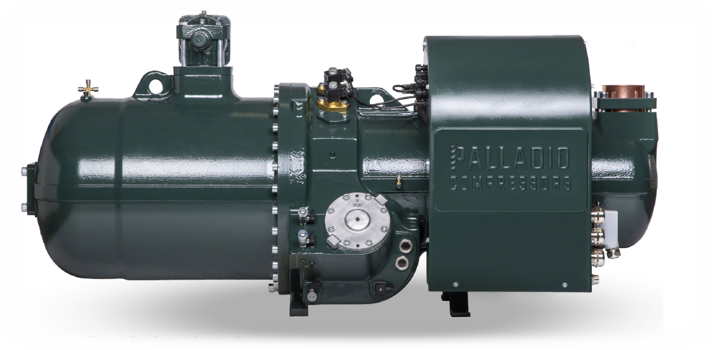
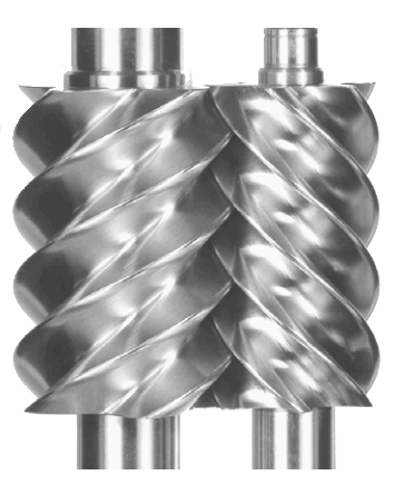
The more usual form has twin meshing rotors on parallel shafts . As these turn inside the closely fitting casing, the space between two grooves comes opposite the inlet port, and gas enters. On further rotation, this pocket of gas becomes sealed from the inlet port and moved down the barrels. A meshing lobe of the male rotor then reduces the pocket volume compressing the gas, which is finally released at the opposite end, where the exhaust port is uncovered by the movement of the rotors. Various combinations of rotor sizes and number of lobes have been successfully employed. In most designs the female rotor is driven by the male rotor, and a study on optimizing rotor design for refrigeration applications is reported. Lubrication, cooling and sealing between the working parts is usually assisted by the injection of oil along the length of the barrels. This oil must be separated from the discharge gas and is then cooled and filtered before returning to the lubrication circuit.
Leakage losses are a function of tip speed, so that smaller machines need to operate a higher speed to maintain efficiency. With synchronous motor drives, this sets a lower practical limit on the size .In all screw compressors, the gas volume will have been reduced to a preset proportion of the inlet volume by the time the outlet port is uncovered, and this is termed the built-in volume ratio. At this point the gas within the screws is opened to condenser pressure, and gas will flow inwards or outwards through the discharge port if the pressures are not equal.
The absorbed power of the screw compressor will be at its optimum only when the working pressure ratio corresponds to the built-in volume ratio. The over and under compression losses can be visualized as additional areas on an indicator diagram . This results in an IE characteristic having a strongly defined peak. To the left of the peak, over-compression of the gas results in loss of efficiency, whilst to the right, there is under-compression with back flow of gas into the compression pocket when the discharge port is uncovered. Changing the size of the discharge port changes the position of the peak . A screw compressor should be chosen to have a volume ratio suitable for the application. Leakage also contributes towards efficiency loss, but friction effects are quite small. Capacity reduction of the screw compressor is effected by a sliding block covering part of the barrel wall, which permits gas to pass back to the suction, so varying the working stroke . It is usual for the sliding part of the barrel to adjust the size of the discharge port at the same time, so that the volume ratio is at least approximately maintained at part load. Many design variations and control methods exist. The single screw type will generally have two sliding valves; lifting valves are sometimes used instead of slides. Reduction down to 10% of maximum capacity is usual. The oil separation, cooling and filtering for a screw compressor add to the complexity of an otherwise simple machine. Liquid injection is sometimes used instead of an external oil cooler. Some commercial screw compressors have the oil-handling circuit built into the assembly.
SPECIAL FEATURES
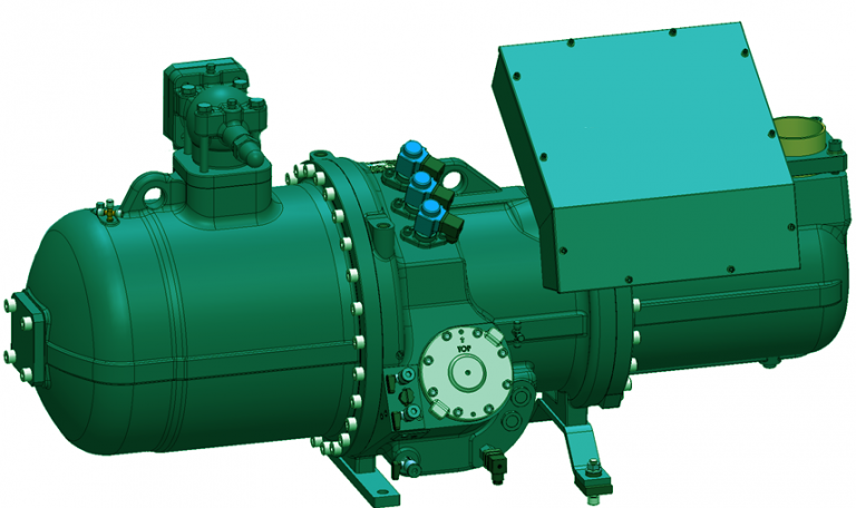
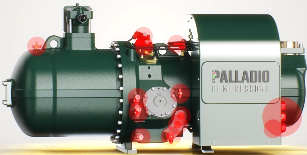
One compressor version suitable for different refrigerants, customized in terms of motor size and Vi (intrinsic volumetric ratio) to achieve the max level of efficiency.
Thanks to the consolidated experience in the after-sales activity, the layout of the compressor has been designed to permit easy check and maintenance operations.
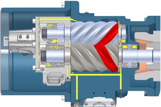
The use of oversized suction bearings and enlarged male rotor shaft grant a safer operation and a prolonged compressor life
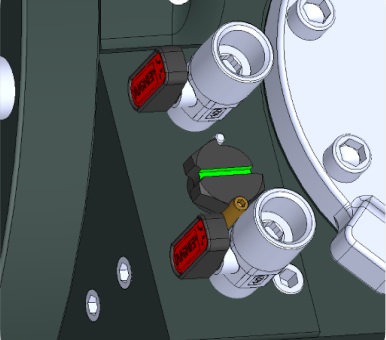
A smart oil interception device permits the addition of an eventual oil cooling heat exchanger or an oil flow switch without additional complicated operations.
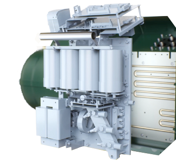
with innovative Tuning system to maximize efficiency while operating condition changes , independent electronic components divided by heavy duty applications , inverter cooled down by refrigerant ,ultra – compact and integrated DC – link choke .
if you have any question about product detail please
MARKETING POLE GROUP
Central Office TEL: 0098 5138407354
Email : info@marketingpole.com